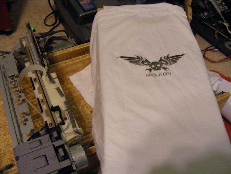
For those unaware, the little acronym above stands for Do-It-Yourself-Direct-To-Garment printing. In layman’s terms, printing your own shirts and designs. Commercial DTGs can cost anywhere from $5,000 to $10,000 which for the hobbyist who only wants a few shirts is ridiculous. So you would think this field of technology would be hacked to no end, but we’ve actually only seen one other fully finished and working DIYDTG. So we took it upon ourselves to build a DIYDTG as cheaply and as successfully as possible.
We would like to take this moment to thank [makemygraphix] for his original designs, as ours is heavily based off his. And Tshirt Forums, for their valuable input.
For your own DIYDTG you’ll need a few parts, (we honestly just used what we had lying around)
-3/4 inch particle board/plywood/MDF
-1/2 inch particle board/plywood/MDF
-1/4 inch plywood
-1 and 1/2inch wood screws
-24inch ball bearing drawer track
-scrap aluminum (1/16″ thick)
-Epson printer (more on this below)
The printer you choose is the most absolutely crucial part of this hack. We took apart an HP DeskJet 3845, Canon iP1500, Brother MFC420CN, Epson Stylus Photo 820 and an Epson Stylus c40. Why so many? We literally purchased every printer the local thrift store had (at $6 a printer, it’s not that bad actually), that way the reader wouldn’t have to. Our findings were thus; the HP and the Canon both had rotary encoders on the paper feed shaft and ended up being a total peta to try to align and get working, both not recommended. The Brother was an all-in-one that would not function unless every part was connected, making it too large and bulky for our needs. Both Epsons used stepper motors, were very easy to take apart, and only had one easy to manage paper sensor. Go with Epson! (We ended up using the C40 because it had the 3 ink CYM system instead of the 5 CYMLCLM system the 820 did).
As for the ink you will be using in your printer, we found DTGinks.com to be a good resource.
For software for your Epson, we found the default drivers worked well enough. There is RIP software out there, but we couldn’t find any that supported the c40. We will recommend the SSC Utility program though. Allowing you to quickly and easily lie to the printer about how much, what kind, and replaced ink cartridges (for Epson only).
For tools we recommend the following
-measuring tape
-square
-pen/chalk line
-table saw
-circular saw
-jigsaw
-Dremel
-drill press/drill (and an assortment of bits)
-sand paper/file
We started off by taking apart the printers. Every printer is different, so we can’t give you details but its relatively simple process. By the end you’ll only need the head and its carriage, the paper feed motor and its shaft, and the power supply.

You’ll need to cut the wood as follows, (it should be noted, these are slightly different then what we actually used)
For the 3/4 inch,
1 x 26inch by 11 and 1/2 inches.
1 x 26inch by 10 inches.
For the 1/2 inch,
2 x 26inch by 5inch,
2 x 26 inch by 1 and 3/4 inches.
First clamp the two 26″x5″ boards together. Now 6″ from the end and 2″ and 3/8″ from the bottom drill a 5/8″ hole through both boards at the same time. This is where your paper feed shaft will go.
Here is a tricky part, the metal track. We mounted the outer part 3/4″ from the top on one of the 26″x5″(doesn’t matter which you choose) pieces and made the stop/back/end of the track flush with the end of the board (this isn’t very high priority) . And the inner part of the track goes 1″ and 1/8″ from the top on one of the 26″x1 and 3/4″ pieces.
Normally we do recommend that you use metal “L” brackets to attach corners of wood, but as long as you pre-drill a hole slightly smaller than your screws, you’ll be fine (we also counter sunk most of our screws, but that’s optional). Attach the two 26″x1 and 3/4″ to the 26″x10″. Do the same with the two 26″x5″ and the 26″x11 and 1/2″ pieces.
All that was a little tricky, so here is a picture to help out. For those wondering, the top tray rolls “towards” you in this image.

And a shot without the top tray, as you can see our shaft wasn’t long enough, so a simple 2″x3″ piece was put in place. Make sure the shaft spins freely and without binding, with and without the top tray in.

The next interesting part is mounting the drive motor. It needs to be snug against the gear of the shaft, yet not too tight to make it grind against the wood. It also needs to have a way of preventing the shaft from “popping out”. We solved both problems relatively simply.
Take your assembly, remove the top shelf, and prop it on its side. Position your motor where it will be mounted on top/inside the 26″x5″ piece. Drop in the shaft, get everything aligned and draw a circle around the motors base. Using a straight edge and tangent lines you can approximate the center of your circle.

Use a large hole saw cut it out (it doesn’t have to be perfect). Sand/file it so the motor easily fits in without bending any pins. We pop riveted a 1″x3″ piece of aluminum to the motor to make mounting a little easier.

Drop in your shaft and make sure everything lines up. Finally, to prevent the shaft from slipping in, we used the washers and C clamp from the extra printer parts (you didn’t throw away, right?) on the other 26″x5″ piece. And to avoid the shaft from slipping out we took a 1″x10″ piece of aluminum, bent it in a “_n_” shape, drilled a hole for the shaft, and used a cut up spring from the extra printer parts. A picture is worth 1000 words,

Bare with me, we’re almost done!
You’ll need to modify the printer carriage now, simply cut off the slot that paper used to come through,

You’ll want to mount it on-top of the two 26″x5″ pieces about 6″ back. We were lucky and found two of the previous mounting screw holes on the carriage fit perfectly, however other printers you might need to bend or make your own. (This picture taken before we made our nifty “_n_” bracket).

Now we made our platen, this is the thing your shirt goes on. It’s really up to you how its made, and we’re not even totally happy with our design, so play around and find what works best. Ours is 24″x9 and 1/2″ piece of 1/4″ plywood mounted to the top of two 20″x2 and 7/8″ pieces of 1/2″ plywood. The height measurement completely depends on the height of your head. For those wondering, we never got an answer for how far the shirt should actually be from the head, but we’ve found about 1/8″ works well enough. (The “legs” you see on our platen were later taken off.)

Mount your power supply and solder it, alongside your motor, to the driver board.

Now there is one part we’ve neglected to mention until now. And that is the paper feed sensor (remember that one sensor we mentioned earlier?). Well it’s because we spent 3 days trying to get that sucker to work with our platen. We tried everything, different timings and positions of the platen, even programming an MCU to try to trick the printer into thinking the platen was paper. In the end, we just broke it off.
By accident.
And it worked (no really!) It takes a little timing on our part but by hand to trigger the sensor, but we’ve never had a misprint like we did with the platen. (Pictured below, one of our “tape” attempts at triggering the paper feed sensor, this one worked about 1 out of 50 times).

Powered on,

Send a print job, hand trigger the paper feed sensor, and we have a print!

Here is just a short video if it in action, most notably you can see us hand triggering the paper feed sensor. The orange was a test print, as you can see if your platen isn’t 100% flat and level relative to the head, you’ll get some smudging and general print errors. The white shirt was a perfect (well, test) print that we did a little earlier.

(Yes, we know the video was blocked earlier. We have re-uploaded it, thank you for your patience; it should work now.)
*Disclaimer, using tools without proper ear and eye protection can result in a visit to the hospital. And HaD is in no way responsible for any damages. Be smart, be safe.*


